|
| |
Index
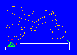
Description of dynamometerDynamometer consists on a metallic structure in which the bikes are placed through a ramp. Bike is tied to the dynamometer by the front wheel through a clamp that can be moved ahead and back with the purpose of fitting the position of the back wheel. This wheel is placed over a solid roller of steel that is fixed on the structure with two bearings. Go to topDesign of the rollerThe roller acomplises a double mission, on the one hand it receive the power that provides the wheel to him and by another one it absorbs and it stores this energy in form of angular velocity, is to say acts of inertial wheel. The characteristics that must have an optimal roller are:
The roller is a drum with serious inertia, thus is better to build
a roller of great diameter and with mass moved away of the axis, nevertheless,
due to wheel is directly tractioning on the roller, the angular velocity of the
roller is a function of the diameter, if diameter is smaller then angular velocity
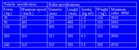
is greater. As can be deduced, that the two characteristics that we had marked ourselves are opposed and is necessary to reach a commitment solution. As we needed that the roller rolls very fast is evident that the tests must be made in last gear. Nevertheless the roller does not have to roll faster of 5000 rpm. by mechanical limitations, therefore the commitment solution is a diameter to which one bike never surpasses the 5000 rpm in last gear. Under this criterion the following table has been made.
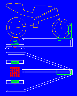
Go to topDynamometer Plans
Go to topInstallation of sensorsThe main sensor that should be mounted on the dynamometer is the pickup to measure roller speed, and then torque and horsepower. This sensor generates an impulse whenever it passes a ferromagnetic body in front of its zone of sensitivity. We will can make a single mark per rev. by drilling the roller in one side. Also, a toothed gear from a starter engine can be mounted to generate a pulse train. Go to topData acquisition and SoftwareOnce we have the finished mechanical part we needed to acquire data and to process them to obtain the curves. For it we will use SmartPower SP-1. Go to topDoing the first test[Go to examples tests made with SmartPower SP-1] Go to topinfo@sportdevices.com to contact SportDevices.com |