|
|
||
|
****JavaScript based drop down DHTML menu generated by NavStudio. (OpenCube Inc. - http://www.opencube.com)****
|
||
|
|
||
|
****JavaScript based drop down DHTML menu generated by NavStudio. (OpenCube Inc. - http://www.opencube.com)****
|
||
Here, this input is used to temporary switch-off the power supply while the PIC activates the SCR to discharge capacitor. When line is 0 volt, the oscillator is ON, when line is higher than 1 volt, oscillator stops. This is done for two reasons: 1. To increase power economy, all power supplied during discharging is wasted. 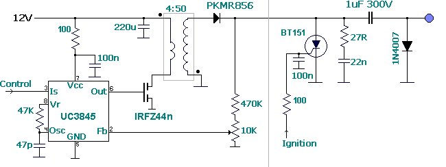
This DC-DC converter charges a 1uF capacitor at 250 volt in aprox. 1 msec. This theorically lets the CDI spark near 1000 times per second, 60,000 rpm in a single cylinder engine (1 spark per rev), 30,000 rpm rpm in a 4 cylinder engine (1 spark each 2 revs per cylinder).
Energy performance is about 85%. For example, at 12,000 rpm in a single-cylinder engine, with a 50 mJ load is equivalent to 12000/60*0.05=10 watt, with 85% performance it is equivalent to 11.8 W (1 amp)
This inverter uses a SMPS (switching mode power supply) oscillator to convert from 12 volt to 200-300 volt range. It uses the flyback topology instead of typical forward converter. When the MOSFET is activated the transformer begins to accumulate magnetic flux and a negative pulse is present (and not used) at the secondary coil.
When MOSFET is turned off, the magnetic energy stored inside transformer is converted to a positive pulse in the primary coil (and not used), close 50 volt, and thus is multiplied by the transformer ratio in the secondary (close 300 volt). This high voltage pulse is used to charge the CDI's capacitor through a high speed schottky diode.Flyback topology lets a wider range for transformation better than forward conerter, by changing the duty cycle. In addition it prevents the "short-circuit" effect while the capacitor is not yet loaded. As in CDI schematic capacitor is continuously charging and discharging, performance is very bad with a standard forward converter. While voltage inside capacitor is low, the transformer is sawn as a shorcitcuit by the mosfet, dissipating a lot of heat.
The SMPS oscillator has two inputs:
Voltage feedback is used to reach the desired voltage, when voltage in capacitor divided in the potentiometer reachs the reference voltage, the oscillator stops.
Current sense input is normally used to control the maximum current in the mosfet. It depends on transformer inductance and oscillator frequency, but not on load.
2. SCR needs the current to be zero to self-disconnect. If power supply stills active, risk of permanent SCR activation exists.
Power stored in capacitor is a function of V and Capacity: E (jules)= V^2 * C.
For example: for 1uF capacitor, charged at 250 volt, E = 0.0625 J = 62.5 mJ.
Values around 50 mJ are standard, values higher than 50 mJ are high power
The last 1N4007 diode is necessary to load the capacitor with the current provided by the transformer. Please note that this current is high frequency and the small 22n capacitor at the left side of the cap. is needed to convert the high frequency of the transformer to DC because the 1N4007 diode is slow.
Last modified: MAR/4/2007