|
|
||
|
****JavaScript based drop down DHTML menu generated by NavStudio. (OpenCube Inc. - http://www.opencube.com)****
|
||
NEW! SportDevices Dumper Analyzer
|
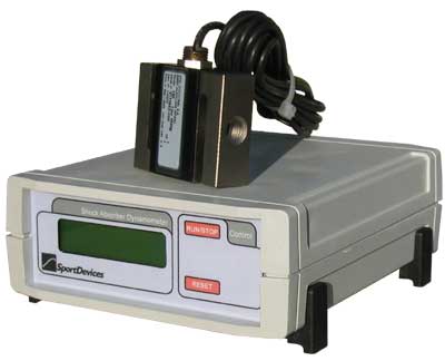
Shock Absorber kit: electronics, software and sensors (load cell and toothed disc included) Price: 1595
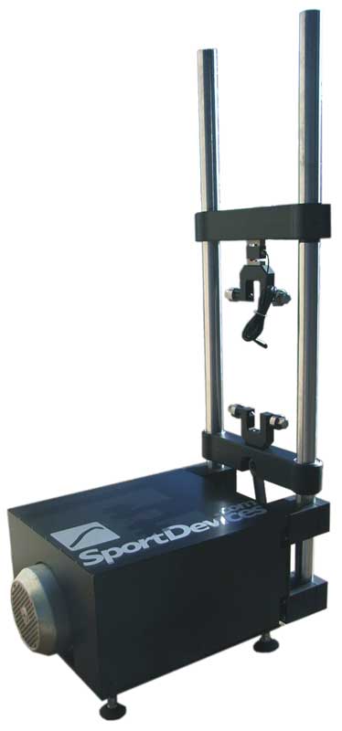
Shock Absorber machine: full tested and working machine with 5.5hp motor and 1000kg load cell Price: Consult
|
|
Features
|
|
|
|
|
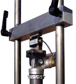
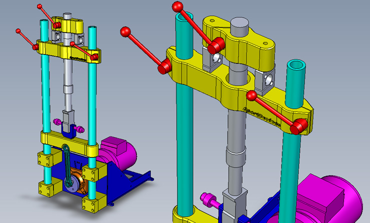
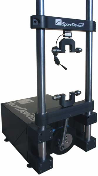
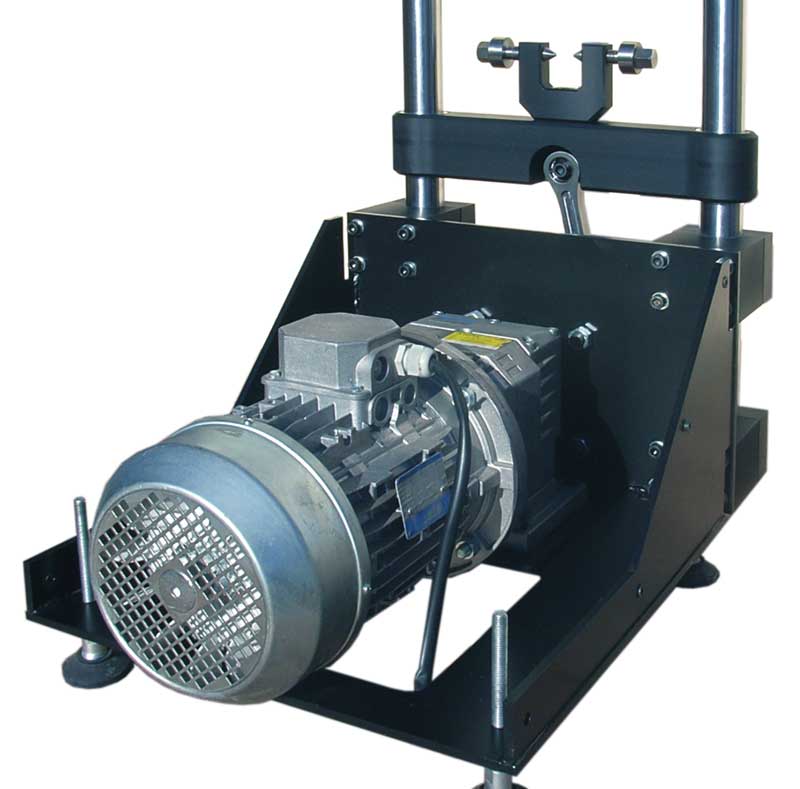
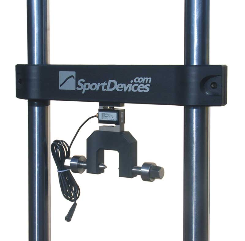
Shock Absorber dynos today:Until now, there are many manufacturers of damper dynamometers. Each company has designed their own model. The one thing common to these models is the price. Most of the machines cost from $20,000 to about $40,000 USD, depending of the options you chose. The market for this expensive equipment has been the larger race teams. Unfortunately, for the smaller and lower budget teams, the price has been simply too much. Mechanical:The shock dyno consists of a metalic main structure, a motor with gear box to reduce motor speed, a scotch yoke or a piston-crank slider mechanism to cycle the shock, and a computer with Dumper-Analizer-Software installed and SportDevices-DumperDAQ. The software adquire data and display graphs of the test. It will also save individual test results and allow to overlay a various tests to compare performances. It is easy to build with industrial devices and it is simple to use. The structure will consist of a strong steel frame with two vertical cylindrical beams. The two cylindrical beams will be tied together with a strong top beam, to which the load cell will be bolted. The load cell will have an adapter for bolting the shock to it. The main frame will act as a mount for the motor, gear box and the two cylindrical shafts. A velocity sensor is installed in the output shaft of the gear box to measure the velocity of the shock. Typical shock dyno characteristics
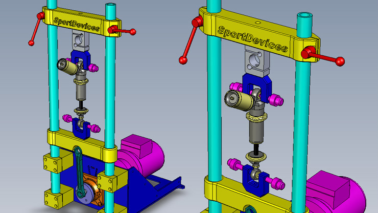
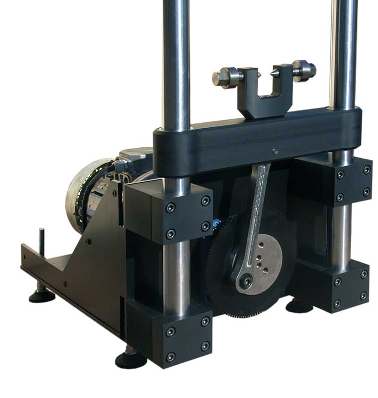
ComponentsElectric Motor Mechanical dynamometers are usually powered by 3-phase AC electric motors. The motors size and power is limited to its supply voltage. For applications up to 2hp, the motor can be powered by the usual mono-phase power source. Larger motors in the 2hp to 10hp range can be powered by 3-phase power source. The motor can be connect to a variable frecuency drive to allow the user to cycle his shock at variable cycles/minute to test diverse speed range. Variable frecuency drive ussualy allow to connect 3-phase motors to mono-phase mains supply. Gear box The output from the motor is geared down, using toothed belts or gears. The output shaft speed could be 300 RPM. Mechanism
Position Gear tooth Dyno hardware use a n-1 gear tooth to meassure speed and position, this part is supplied with the kit. Stroke length selector There are ten screewed holes located over spiral shape, connecting rod can be fixed in any hole to select stroke length. The longer the stoke, the greather the power needed on motor to move the shock absorber. At higher stroke, it is possible that the motor couldn't move the shock absorber, thus we recomed to start at position 1 and increase it step by step.
Shock temperature sensor Shock temperature is measured using a temperature sensor attached to the casing of the shock with a Velcro strap. Shock performance can vary dramatically at different temperatures. With the temperature monitoring system, you can determine how your shock will proform under various temperatures. You can warm the shock directly on dynamemeter. How are it used?Shocks are bolted into the dyno unit on the provided mounting locations. The stroke and motor speed is set to a chosen speed range (If you don´t have variable speed drive, speed range only can be select by stroke length setting.). The computer is set up to receive the data and the initial temperature is taken. The machine is then started and the shock is cycled into the chosen velocity range where the data is sent to the computer. The computer can then display the data in a graphical method that will allow the operator to adjust the shocks accordingly. For example, if a vehicle is coming out of the turns too tight the operator will run the shock on the dyno to check the setting. The shock is then rebuilt to loosen up the shock and ran on the dyno again. With the proper expertise, the shock can be reinstalled on the car with the desired characteristics. New SportDevices Design:
contact: info@sportdevices.com SportDevices.com
12/11/07 |