|
|
||
|
****JavaScript based drop down DHTML menu generated by NavStudio. (OpenCube Inc. - http://www.opencube.com)****
|
||
|
|
||
|
****JavaScript based drop down DHTML menu generated by NavStudio. (OpenCube Inc. - http://www.opencube.com)****
|
||
RPM READINGSIn the next pages some sensing circuits are explained. These circuits are currently under test and will be added soon to the base SP1/SP3 products to ease the task of reading ignition on engines In addition, some ignition systems are explained, and how to read ignition with them Capacitive RPM sensing circuitThis is the current RPM sensing circuit on the SP1. Ignition pulses goes through the HV cable to the capacitive clamp, and they arrive to the rpm connector on the SP1. There, the signal goes to the top layer of the board and is transmitted by the board capacity through the bottom layer of the board, and then it enters on the circuit.  This is the current ignition circuit in the SP1/SP3 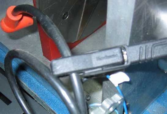 capacitive pickup Inductive RPM sensing circuitCurrent from ignition pulses creates an magnetic field inside the RPM pickup, and this is transformed into a current pulse inside the pickup coil. The pickup pulse is aplied directly to a SCR (thyristor) that discharges completely the inner capacitor on the SP1, this cause filtered pulses in the line that goes to the SP1 to avoid other short pulses to fire it. The other components placed with the SCR are provided to filter the pickup pulses. Only current pulses should fire SCR. If you place the inductive pickup near a HV cable, it will catch HV pulses, or EMI pulses. This pulses go through the pickup cable to the conditioning circuit as common mode signals (inside the two wires), but are filtered with the 10 nf capacitor and the resistor to prevent the SCR to be fired. The 22 pf capacitor, 100K resistor, 1N4148 diode and BC547
transistor has been removed from the current sensing circuit inside SP1. One 47
nf capacitor has been add to prevent the NE555 to be fired with gliches in the
line. Only pulses caused by the MCR100 SCR will discharge the capacitor and
then will fire the NE555.
 Inductive sensing circuit. Click here to go to the upgrade guide 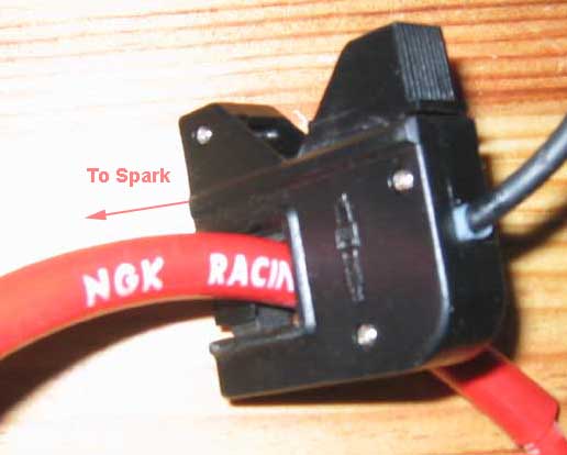 Inductive pickup This circuit "measures" ignition current, so it only will read such
current pulses of certain level. When used on wasted spark ignitions, two situtacions
are present:
1) When engine accelerates, one spark happens when engine is compressing the air-fuel
mixture, and then pressure is present inside the cylinder, and the spark needs more
voltage to cross the gap, so high energy is present in the HV cable.
The next spark (in the same cylinder) happens when engine is in exhaust phase, then the exhaust valve is opened and then low pressure is present inside the cylinder, thus low voltage is needed to cross the gap, and then the ignition energy is low. Theorically both pulses have the same current but due to a parasitistic capacitive effect each pulse is sensed with different amplitude.  2) When engine is running at high speed, and throttle is closed suddenly,
all sparks happens when engine has low pressure, because the throttle is closed and only a few
air-fuel mixture is present.
Thus all sparks have low current, and the SCR circuit only senses a few of them. This is shown at the Dynamometer software as a failure on the rpm channel.   Capacitive sensing circuit to be used with modified SP1/SP3 units Click here to see some sample tests recorded with these circuits |
|
Cylinder to get spark is selected with a distributor. This schema is obsolete. To read RPM in this schema, you only need to place the capacitive clamp on the main HV cable (from coil to distributor). This will pick all RPM pulses (2 sparks per rev), thus you should select "/2" option on the program to get the actual rpm value. click here to see a sample test
|
|
Two cylinders are fired at the same time. One of them is in compression phase, and it fires the air-fuel mixture when spark is made. The other cylinder is in exhaust phase, and spark has no effect over it. To read RPM in this schema, you only need to place the capacitive clamp on any of the outter HV (1 or 4) taking care that the sensing cable doesn't touch the other HV cables to prevent to catch pulses from the other coil. This will pick RPM pulses from one coil (1 spark per rev), thus you should select "x1" option on the program to get the actual rpm value. If pulses from the other coil are often (but not always) catched, readings will be unaccurate. One solution may be to catch wire 1 and wire 2 with the rpm pickup. In this case "/2" option should be used click here to see a sample test |
|
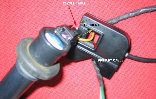
In this schema each spark has its own coil, and there is no HV cable from the coil to the spark. This schema can be used both for TCI and CDI ignitions. The ECU can fire each spark one by one. To read RPM the difficulty with the current capacitive method is that the HV pulse is made inside the coil and there is no HV cable, so it is difficult to catch the ignition pulses with the capacitive clamp. A thick wire can be placed inside the coil going outside it, so the capacitive clamp can be placed over it. If using an inductive pickup, the current pulses in the coil cables can be read with the pickup. These pulses use to be higher than on HV cable, so readings should be good. Keep in mind that these cables have polarity, one of the is 12 Volt, and the other is switched to ground to charge the coil, so the current only flows in one sense.
How is placed the inductive pickup on the primary?
click here to see a sample test |
|
The two cylinders are fired at the same time (equal as wasted spark), but the firing time is not always the same because the cylinders are in V configuration. When Cylinder 1 is compressing the mixture, cylinder 2 is starting exhaust phase, so spark in cylinder 2 has no effect. And when cylinder 2 is compressing, cylinder 1 is ending exhaust phase, but no new air-fuel mixture has started to enter, so spark in this moment has not effect. When read timings it seems to be not steady. For example at 3000 rpm (20 ms), timing will be: 25 ms, 15 ms, 25 ms, 15 ms, and so on... We has solved this problem in the SP1 and SP3 by group always two samples: (25 + 15)/2 = 40 / 2 = 20 ms -> 3000 rpm and if sequence is taken backwards it works too: (15 + 25)/2 = 40 / 2 = 20 ms -> 3000 rpm no sample, at the moment |